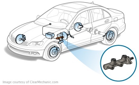
The main brake cylinder shall convert the pressure of the driver to hydraulic pressure in the contours of the braking system. Hydraulic part of the braking system
Hydraulic part of the braking system
The hydraulic part of the braking system consists of the main brake cylinder, cylinders and brake tubes. There is a liquid in the brake tubes which transmits the brake actuation force to the brake pedal. In order to carry out the transfer, the mechanical pressure shall be converted to a hydraulic pressure first and then distributed to the four braking devices. For this, there is a master brake cylinder or GTZ.
The safest two-circuit braking system is diagonal. Such a scheme prevents oversteer from single work circuits
Modern braking systems are equipped with a double-circuit major brake cylinder. Each cylinder of a cylinder is connected to a separate circuit of the braking system. This is necessary for safety-if one circuit fails, the second will stop the car, albeit with less efficiency. Each contour serves one front and one rear operating mechanism, diagonally (for example, the right rear and left front). Two decades ago, the diagram was different-the front cylinders were connected to the same path, and the rear cylinders were connected to the other. Gradually, the manufacturers have renounced this system because of low resistance to a single stroke in the case of braking.
In a modern car, the general hydraulic structure includes the ABS system, the servo brake system, and a number of other improvements
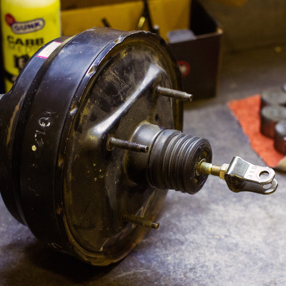
The main brake cylinder may be combined with a container containing brake fluid into a single design or installed separately and connected to a tank through hoses. The main brake cylinder is fitted to the vacuum amplifier of the brakes (present in the brake system of the vast majority of modern motor vehicles).

The brake fluid drums shall be made of transparent material so that the driver can visually monitor the level of the brake fluid. A level sensor is also installed in the brake cover plate that signals a drop in the level of the brake fluid (lamp or diode on the instrument panel).
In the event of a leakage from the contour of the braking system, the liquid from the brake system enters the cylinder by replacing the loss.
Master brake cylinder device
The master cylinder shall consist of a steel cylindrical shell with two pistons situated within two pistons, one per circuit. A rubber cuff shall be used to provide compaction between the cylinder and the pressure. Each piston has its own return spring. Limits the piston to the piston holes in the hole at the bottom of the cylinder.
In the US, the use of the two-end system of brakes is mandatory since 1967
In the body of the master cylinder, there are threaded holes for the addition of two contour tubes (two tubes per cylinder, one for each cylinder). Internally, a compensation outlet is provided to equalize the pressure of the liquid in the cylinders of the cylinder.
Plan of work of the master cylinder of brakes
The pedal force shall be applied to the cylinder through the vacuum amplifier of the brakes. Pressing the brake pedal starts to push the piston of the first circuit, the piston is moving forward, the cuff overcovers the countervailing hole, and the contour starts to increase the pressure. The pressure used to move the piston of the second circuit, which also brings up the pressure. The vacuum produced by removal of the piston shall be filled with the brake fluid from the outlet. The movement of the piston continues until they reach the limiters.
In the Toyota Prius with the hybrid actuator, the main brake cylinder is several times longer, since the role of the main brakes is taken over by the [ [ engine-generator]] s
Once the brake pedal is released, the pistons shall be returned to their original position under the action of the return spring. When the piston is in the rear, a compensation hole is opened and the pressure in the cylinder is flattens.

Even if the driver, for some reason, abruptly "drop" the brake pedal, this will not cause a differential pressure, as the excess fluid from the cylinder will return to the container.
The main brake cylinder is designed in such a way that if any leakage occurs in one of the contours, the second circuit will continue to operate. For example, if the leak occurred in the first circuit, when the brake pedal is pressed, the piston of the first cylinder will simply "leak" its contour to the second piston. The piston of the second circuit will begin to move forward and create the pressure necessary to activate the second circuit.
The main brake cylinder is not only worn but also rusting away from the inside. The fact is that the brake fluid contains a small amount of water and oxygen
If the leakage of the brake fluid is observed in the second circuit, the actuation of the master cylinder will look slightly different. When the first piston is in motion, it involves the piston in motion of the second contour, and the piston shall begin to move forward without interference until the end of the circuit is blocked by the outlet. The first circuit is followed by a pressure of the first circuit to braking the wheel mechanisms of the first circuit. During leakage in one of the contours, the brake pedal will "fail", but at the end of the stroke effective braking will begin.
Brake cylinder defective brakes
The malfunction of the master cylinder is expressed in wear or damage to the piston in the piston, as well as the compression cuff at the inlet of the cylinder. This should also include the withdrawal of the return springs of the piston, the bullies of pistons, or the wear of the mirror of the cylinder.
The defective elements of the cylinder shall be replaced, and if the mirror is damaged, the master cylinder of the brake shall be replaced.


